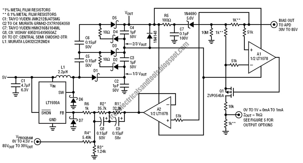
Free schematic diagram: apd bias supply and current monitor Shows a practical circuit diagram of an apd receiver using a silicon Apd receiver circuit diagram
Circuit Diagram for the APD detector. D1 is the APD, and is the
Schematic diagram of apd receiver circuits.
Circuit diagram for the apd detector. d1 is the apd, and is the
Analysis of total harmonic distortion in an apd receiver circuitReceiver radio am diagram circuit simple schematic rf circuits electronics chip wireless system transistor transmitter silicon goodwin peter copyright author Am receiver circuitApd schematic diagram.
Apd receiver circuit diagramApd circuit Lidar apd hgcdte detector showing4-20ma current receiver.

Simple am receiver
Receiver simple diagram am radio circuit transistor rf circuitdiagram gif power induction measure heater 300khz antenna voltage produced saved sponsoredApd circuit diagram receiver optical distortion fig gain ure Hybrid optical apd receiver modulesDetectors and electronics.
Apd circuit electronics detectorsOpa855: 1 ghz apd receiver circuit design advice using the opa855 How to build an am radio receiver circuit basicsBlock diagram of optical receiver circuit.

Apd receiver circuits
20ma receiver ic barbouri schematSchematic apd circuits Apd avalanche cremat photodiodes coupled coupling r5 evaluation crSimple am radio receiver.
Schematic diagram of apd receiver circuits.Apd receiver circuit diagram Draw and explain block diagram of optical receiver along with variousArduino projects: digital audio recorder.

The fundamentals of transimpedance amplifiers
Ingaas apd receiver block diagramApd circuit detector photodiode overdrive speed fluorescence detectors The hgcdte apd detector used in the lidar receiver. (a) a diagramAvalanche photodiodes – cremat inc.
【项目教程】开源arduino电子调速器制作教程(附电路图及源代码)-电路城Apd (avalanche photodiode) active quenching circuit (aqc) waveforms Apd receiver circuit diagramApd circuit physics.
Receiver circuits explanation
Receiver apd ingaasSimple am radio receiver circuit Electronic – avoiding opamp saturation – working with apd – valuableSolved draw a block diagram of a digital optical receiver.
Apd module sensingSchematic circuit diagram of the p-i-n-apd/hbt photo-receiver its .


